
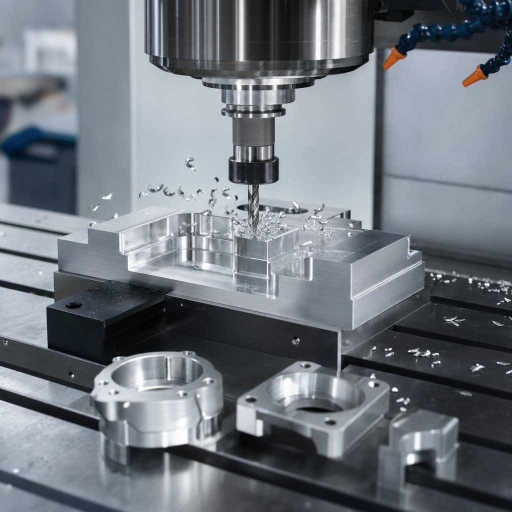
Aluminium machining is the process of cutting solid aluminum stock into finished parts by removing material in a controlled way. In both British and American usage, aluminium machining and aluminum machining describe the same family of subtractive methods, including CNC milling, drilling, turning, and routing. Manufacturers use it when parts need low weight, good corrosion behavior, and broad design flexibility without giving up precision.
Many teams machine aluminium for brackets, housings, frames, and fixtures because it cuts cleanly and supports attractive post-finishing. A dense, self-protecting oxide layer, noted by Protolabs, is one reason aluminum performs well in environments where corrosion resistance matters.
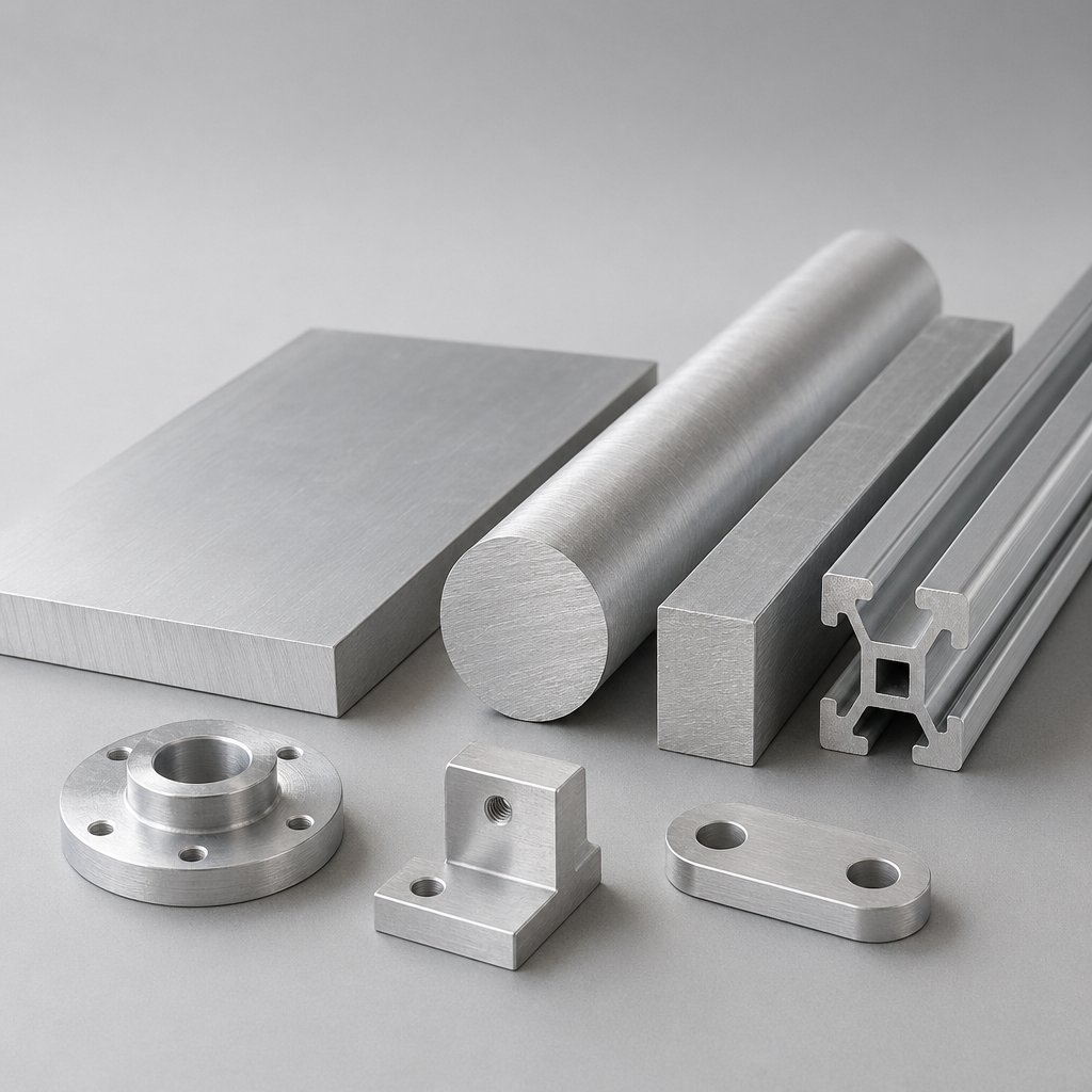
Aluminium machining is the subtractive shaping of aluminum plate, bar, billet, or extrusion into precise parts through CNC milling, drilling, turning, routing, and related cutting operations.
In day-to-day cnc aluminum work, the goal is not just to remove metal. It is to control chip flow, heat, and tool pressure so surfaces stay clean and features stay accurate. Shop guidance from JLC CNC also highlights why cnc machining aluminum is common in aerospace, robotics, automotive, and consumer electronics.
Compared with steel, aluminum usually places less strain on tools and is easier to cut quickly, while steel is often chosen when higher absolute strength or heat resistance is more important. Compared with plastics, it offers greater rigidity, better heat handling, and cleaner threaded or structural features, while plastics can suit lighter-duty parts but are more sensitive to heat and deformation during cutting. That is why the phrase cnc aluminum covers a wide range of part types, but not a single material behavior. The exact alloy still changes how the job runs.
Material selection changes far more than part strength. It affects chip formation, surface finish, burr behavior, corrosion performance, finishing options, and even whether a plate stays flat after stock removal. That is why the best aluminum for machining depends on what the part must do after it leaves the machine, not just how easily it cuts.
For many general-purpose parts, 6061 sits in the middle of the decision map. Protolabs describes it as a well-rounded choice with good corrosion resistance, weldability, and broad usability, while Mitotec Precision lists 6061-T6 at 310 MPa tensile strength and 95 HBW hardness. That balance explains why machining 6061 aluminum is so common for fixtures, brackets, housings, and structural components.
If strength leads the brief, 7075 and 2024 move into focus. Mitotec lists 7075-T6 at 570 MPa tensile strength and 150 HBW hardness, making it a strong fit for high-stress aerospace or defense parts. 2024-T3, at 470 MPa tensile strength and 120 HBW, also offers strong performance and good machinability, but Protolabs notes its corrosion resistance is poor and it is not suitable for welding.
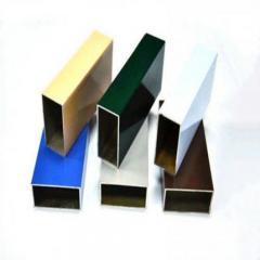
If the environment is wet, marine, or outdoor, magnesium-bearing alloys usually make more sense. Protolabs highlights 5052 for very good corrosion resistance, weldability, and workability, while Mitotec places 5052-H32 at 230 MPa tensile strength and 60 HBW. For decorative or architectural parts, 6063 is often chosen because it combines corrosion resistance with a finish that suits anodizing well.
Flatness can override all of that. Rapid Axis describes MIC6 cast plate as especially flat, stable, and highly machinable for precision work. Protolabs also notes MIC6 can be machined at high speed and is free from tension, contaminants, and porosity. For vacuum tables, tooling plates, and large precision bases, that stability matters more than chasing the highest strength number.
| Alloy | Machinability | Strength profile | Corrosion resistance | Anodizing suitability | Cost positioning | Best-fit applications |
|---|---|---|---|---|---|---|
| 6061-T6 | High, very machinable aluminum for general CNC work | Balanced, 310 MPa tensile, 95 HBW | Good | Good, often used when post-finish matters | Mid-range | General structural parts, housings, fixtures, automotive, consumer products |
| 7075-T6 | Good for precision cutting, but less forgiving in fabrication | Very high, 570 MPa tensile, 150 HBW | Lower than 6061 | Usable, but typically chosen for strength first | Higher | Aerospace, defense, high-stress lightweight parts |
| 2024-T3 | Good | High, 470 MPa tensile, 120 HBW | Poor | Less attractive where corrosion exposure dominates | Higher | Aerospace and durability-focused parts with controlled environments |
| 5052-H32 | Moderate, more often selected for formed or corrosion-facing parts | Moderate, 230 MPa tensile, 60 HBW | Very good | Good for protective finishes | Lower to mid-range | Marine components, tanks, enclosures, sheet-based designs |
| 6063-T6 | Good | Moderate, 240 MPa tensile, 73 HBW | Good | Very good, especially for appearance-driven parts | Cost-effective | Architectural components, heat sinks, profiles needing clean finish |
| MIC6 cast plate | High, supports fast machining and stable setups | Chosen for flatness and stability more than peak strength | Suitable for many indoor precision uses | Not usually the first pick for cosmetic anodized parts | Specialty plate pricing | Tooling plates, bases, semiconductor and precision assemblies |
| General cast plate | Often good when stability is prioritized | Varies by grade | Varies by alloy and environment | Check finish goals before release | Varies | Large flat components, machine bases, fixtures |
Buyers can simplify the choice this way: 6061 for all-around performance, 7075 or 2024 for higher strength, 5052 or 6063 for corrosion and finish priorities, and MIC6 or cast plate when flatness and stability drive the job.
In practice, aluminum for machining is rarely chosen on one property alone. The most machinable aluminum is not always the right one for welding, anodizing, salt exposure, or ultra-flat assemblies. And once the alloy is locked in, the cutting method starts shaping the final result just as much as the material itself.
A smart alloy choice helps, but feature quality is decided at the cut. In machining aluminum, each process handles a different shape, chip pattern, and finish risk. Milling is typically used for flats and internal geometry, drilling for holes, tapping for threads, and turning for diameters and other round features. That sounds simple on paper. On the machine, sharp edges, clean chip flow, and the right lubrication strategy are what keep those features from turning into burrs, smeared walls, or rough threads.
For many prismatic parts, cnc milling aluminum is the main operation behind pockets, slots, and faces. When milling aluminum, the recurring problem is chip recutting. Aluminum milling usually responds best when chips leave the cut quickly and the tool stays sharp enough to shear instead of smear. The same idea runs through the broader machining of aluminum: if chips stay in the cut, edge quality usually drops first.
Drilling needs its own discipline. The Jarvis guide recommends HSS or cobalt drills, with split-point or helical-point geometry and larger flutes to improve accuracy and reduce flute packing. It also stresses lubrication because aluminum tends to stick to the drill and generate heat. Clean surfaces, a spotted location, steady pressure, and deburring after breakthrough all help hole quality.
Tapping raises the tolerance for mistakes. Guidance from CTE notes that spiral-fluted taps are especially useful in blind holes because they pull chips back out of the hole, while form taps produce threads without creating chips at all. High rake geometry, proper lubrication, low runout, and rigid setups support better thread finish and reduce the chance of built-up edge.
| Feature | Best-suited process | Why it fits |
|---|---|---|
| Pockets | Milling | Best for controlled internal material removal |
| Slots | Milling | Allows width, depth, and wall control |
| Faces | Milling or turning | Milling suits flat prismatic faces, turning suits circular faces on round stock |
| Holes | Drilling | Fastest primary method for straight hole creation |
| Threads | Tapping or thread milling | Tapping is efficient, thread milling adds flexibility and burr control |
| Round parts | Turning | Built for diameters, shoulders, and concentric features |
Round work changes the priorities. When turning aluminum, chip control becomes central to finish and consistency. Sandvik Coromant highlights insert geometry, nose radius, entering angle, feed, cutting depth, and coolant delivery as major levers. For thin or vibration-prone parts, a sharp insert and smaller nose radius can lower cutting forces, while an entering angle close to 90 degrees helps direct forces axially. Sandvik also notes that burrs often form at tool exit, and a chamfer or radius can make entry and exit smoother.
Good process selection solves only part of the problem. Tool geometry, coolant delivery, machine rigidity, and clamping pressure decide whether these choices hold up in production.
The same alloy and toolpath can produce very different results depending on setup. In aluminum work, clean walls and stable dimensions usually come from a simple combination: sharp tools, reliable chip evacuation, sensible feed and spindle planning, and workholding that supports the part without distorting it. That is true whether you run an aluminum cnc machine for prototypes or a dedicated cnc aluminum milling machine for repeat production.
Machine capability matters because chip evacuation is often the real limit. Guidance from KSPTG shows why flute count has to match the machine’s ability to clear chips. A rigid, high-RPM vertical machining center with strong air blast or well-directed coolant can support 3-flute tools effectively. Older or less rigid equipment, or any cnc machine for aluminum with weak coolant access, often benefits from 2-flute cutters because the larger gullets give chips more room to escape.
Wevolver also notes that 2-flute tools are commonly favored for heavy roughing, while 3-flute tools offer a stronger core for semi-finishing and light finishing. Carbide is generally preferred because it holds a sharp edge at higher spindle speeds, and coatings such as ZrN, TiB2, or DLC can reduce adhesion between the tool and the workpiece.
| Machine category | Likely use case | Setup priorities |
|---|---|---|
| 3-axis vertical mill | General prismatic parts, pockets, slots, faces | Short tool overhang, strong chip evacuation, practical flute choice |
| High-speed VMC or 5-axis mill | Complex surfaces, reduced setups, lighter radial engagement strategies | Stable harmonics, balanced tooling, consistent air blast or coolant |
| Lathe or mill-turn | Round parts, bores, threads, turned diameters | Insert sharpness, chip control, part support, clean tool exit |
Tool geometry should encourage shearing, not rubbing. For most jobs, that means polished carbide, positive cutting action, and an edge sharp enough to resist smearing. Moderate helix angles are commonly used for balanced roughing, while higher helix tools can improve finish if heat and chip flow stay under control. A cnc milling machine aluminum setup usually performs best when spindle speed and feed are planned together so the tool cuts a chip cleanly instead of skating across the surface. On a rigid cnc mill for aluminum, that often means avoiding timid parameters that promote built-up edge.
A capable cnc milling machine aluminum job still depends on the part being designed for access, support, and realistic tolerances. Thin walls, deep cavities, and over-specified features can overwhelm even a well-prepared cnc mill for aluminum, which is where design rules start driving cost just as much as the machine itself.
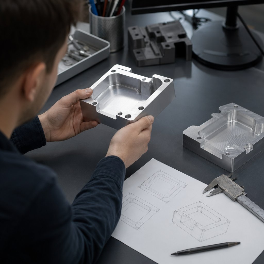
Geometry is where setup decisions turn into dollars. In custom aluminum machining, a part can sit on a rigid machine with sharp tools and still be expensive if the model forces tiny cutters, long reach, or extra setups. Thin walls, deep pockets, and hard-to-inspect dimensions all push up the cost of machining aluminum long before a machinist presses cycle start.
The design guidance published by JLC and Bergek points in the same direction: reduce unnecessary complexity, give tools room to work, and call out only the dimensions that truly control function. That is the core of economical aluminum parts machining, whether you are releasing a fixture, housing, or repeat aluminum machining part.
Most DFM issues are visible in the CAD model if you know what to look for. Internal corners are a classic example. Because end mills are cylindrical, perfectly sharp inside corners usually require smaller tools or secondary processes. In the JLC design guideline, a practical cavity rule is minimum internal radius R = (H/10) + 0.5 and tool diameter D = H/5, where H is cavity depth in mm. Bigger radii are usually easier, faster, and more robust.
Good tolerancing is about selectivity, not bravado. In aluminum precision machining, broad tolerances on noncritical geometry reduce both machining time and inspection time. The JLC guideline notes that when no tolerance is provided, parts may default to a standard tolerance of about ±0.1 mm or higher, and tighter requirements should be defined on a 2D drawing. Published capability examples from Bang Design place general CNC aluminum work around ±0.05 mm for standard features, with much tighter values possible under specialized process control. Those numbers are useful mainly as a reminder that tolerance capability changes with geometry, machine condition, setup count, and inspection method.
Put the tightest limits on mating diameters, positional relationships, sealing faces, and datum-related features. Leave open profiles, nonmating edges, and stock cleanup dimensions looser when function allows. A clear 2D drawing should also call out thread depth, critical areas, surface roughness, and any inspection notes, which JLC highlights as essential for choosing the right process and avoiding mismatches between the model and the print.
Tighter tolerances, deeper features, thinner walls, and cosmetic demands usually mean slower cutting, more careful fixturing, and more inspection. Save that complexity for the features that earn it.
That discipline pays off twice. It makes quotes more accurate, and it removes many of the conditions that later show up as burrs, chatter, smearing, and unstable finish on the machine.
A part can look perfect in CAD and still leave the machine with ragged edges, smeared walls, or visible vibration marks. That is the practical side of aluminium machinability. The material cuts readily, but it also reacts quickly to trapped chips, dull edges, excess heat, and weak support. Shop guidance from TZR and SZ Zuerst points to the same pattern: burrs, built-up edge, poor finish, and part movement usually come from a mismatch between tooling, parameters, coolant, and workholding.
In day-to-day machining aluminium, these defects often stack up rather than appear alone. A thin wall that chatters may also leave burrs at tool exit and shift after unclamping. In cnc aluminium cutting, that chain reaction shows up most often in deep pockets, narrow slots, blind holes, and light sections where chips are hard to evacuate and support is limited.
| Symptom | Likely cause | Practical fix |
|---|---|---|
| Burrs on edges or hole exits | Dull tools, poor tool exit, vibration, or weak clamping | Use sharper tools, stabilize the part, and refine entry and exit strategy |
| Built-up edge and smearing | Aluminum sticking to the cutter because of poor chip evacuation, dull edges, or an imbalanced speed and feed window | Use polished, sharp aluminum-friendly tools and improve chip flushing with coolant or air blast |
| Chatter marks | Long tool reach, aggressive engagement, or weak support on thin features | Shorten overhang, reduce cutting load, and support thin walls more effectively |
| Chip packing | Deep enclosed features, limited flute space, or poor coolant access | Increase chip evacuation, open up the toolpath where possible, and match flute count to the feature |
| Part distortion or size drift | Thermal expansion, tool deflection, or uneven clamping | Control temperature, use shorter tools, and clamp evenly without overloading thin sections |
| Inconsistent surface finish | Tool wear, vibration, recut chips, or inadequate lubrication | Separate roughing from finishing, maintain lubrication, and replace worn tools sooner |
TZR notes that a standard as-machined CNC finish is often around Ra 3.2 μm, while added finishing passes may improve that to Ra 1.6, 0.8, or 0.4 μm. When finish changes from pass to pass, the issue is usually process stability, not looks alone.
When milling aluminium, burrs usually grow where the tool pushes material instead of shearing it cleanly, especially on unsupported edges and at breakthrough. Built-up edge starts when aluminum adheres to the cutting edge and changes the real tool geometry. Guidance from Aluphant ties burr control to sharp carbide tools, polished flutes, climb milling, clean entry and exit paths, and steady coolant flow. TZR also shows that low cutting speed, weak chip removal, and dull edges can trigger built-up edge. That is why an aluminium cutting speed milling chart is only a starting point. Parameters have to work with chip evacuation and part rigidity.
These fixes connect directly to the earlier decisions on alloy choice, setup, and DFM. Softer, more ductile material forms can burr more easily, while thin walls and deep cavities magnify every setup mistake. Sometimes the best way to cut rework is not a better deburring step, but a different starting form altogether for long, repeating geometries.
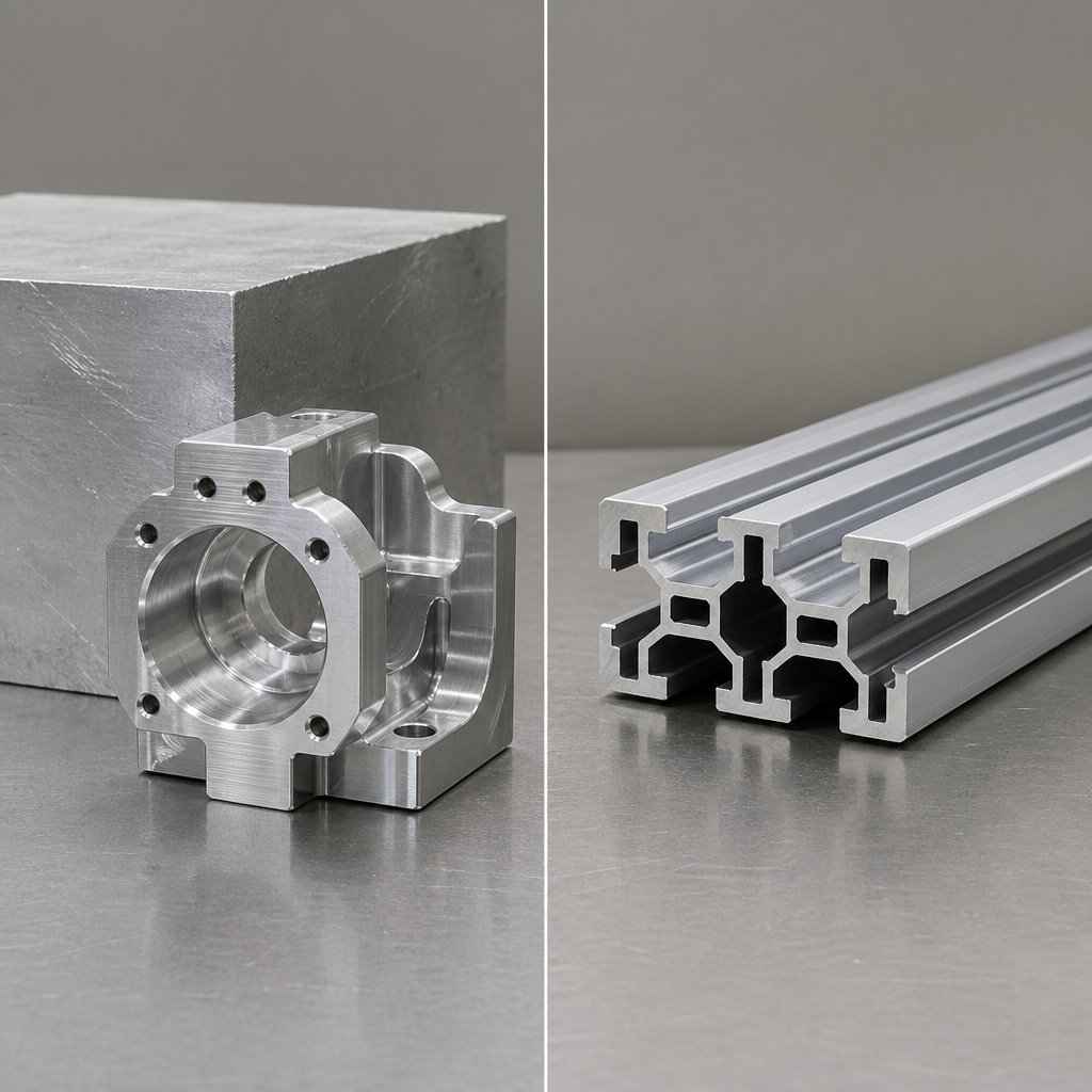
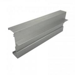
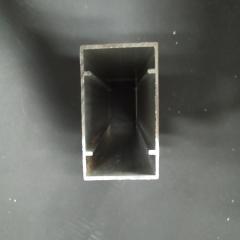
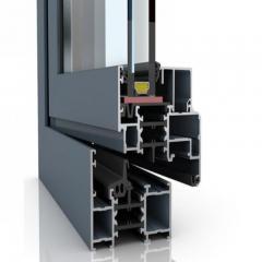
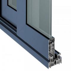
Long, repeating geometry can change the best process before a cutter ever touches the part. If a design starts as one constant profile, extrusion often removes complexity early. If the part needs deep pockets, multi-face features, or tight positional control, machining from a block of aluminum for cnc is usually the cleaner path. In practical aluminum parts manufacturing, the real question is where the geometry lives: along the profile length, or across several faces that need precise cutting.
The ETCN guide frames CNC machining as the more flexible option for intricate shapes and tighter tolerances, while extrusion is inherently tied to continuous cross-sections formed through a die. That is why a cnc aluminum prototype, an aluminum prototype with likely design changes, or large aluminum machined parts with different features on multiple faces often favor billet machining. The same logic makes cnc aluminium prototyping attractive when teams want to avoid upfront die tooling until the design settles.
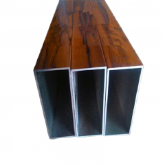
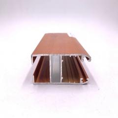
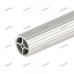
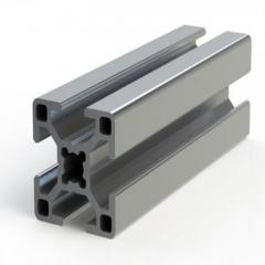
Extrusion becomes compelling when the cross-section repeats and the project can benefit from better material utilization. The same ETCN comparison highlights lower waste and strong fit for structural profiles, while Precision Steel shows how secondary CNC work can add holes, taps, chamfers, notches, and cut lengths after the profile is made. For rails, frames, enclosure bodies, and transport sections, that hybrid route can simplify production. If you need a supplier able to support both routes, Shengxin Aluminum is one relevant example to review because it offers custom extrusion and CNC machining for construction, automotive, and transportation applications.
| Decision factor | Full billet CNC machining | Extrusion plus secondary machining |
|---|---|---|
| Geometry freedom | Best for complex 3D features and multi-face detail | Best for repeating cross-sections |
| Material utilization | More material removed during cutting | Typically more efficient for long profiles |
| Secondary operations | Often completed in the same machining workflow | Usually needs added drilling, tapping, cutting, or notching |
| Finishing flexibility | Strong for feature-specific cosmetic or precision finishing | Strong when a profile needs post-machined details and surface treatment |
| Typical fit | Automotive brackets, transportation hardware, custom housings | Construction frames, vehicle rails, long structural members |
The drawing usually decides faster than any sales pitch. Constant-profile parts tend to lean toward extrusion. Feature-dense parts lean toward machining. Many jobs sit in between, and that is where clear CAD, finish notes, and supplier feedback start shaping the quote just as much as the process itself.
The drawing usually decides the process, but the quote package decides how smoothly the job moves. A supplier can only give useful DFM feedback, routing advice, and pricing when the input is complete. Guidance from MakerStage shows that a complete RFQ can cut quote turnaround dramatically, while missing files or vague material notes often trigger days of back-and-forth.
If you want a faster and more accurate aluminum cnc service quote, send the part as a manufacturing package, not just a model.
Better input data leads to better manufacturability feedback, cleaner quotes, and fewer surprises on the shop floor.
When comparing an aluminum cnc machining manufacturer, look past unit price. The sourcing advice in Procam Services and MakerStage points to the same filters: experience, suitable equipment, dependable quality control, and the ability to match your part complexity.
A strong aluminum cnc machining manufacturer does more than cut metal. It spots risk early, questions unclear notes, and helps keep cost, quality, and process choice aligned before the first chip falls.
Aluminium machining is the controlled removal of material from aluminum stock, such as plate, bar, billet, or extrusion, to make finished parts. Typical processes include CNC milling, drilling, turning, routing, and tapping. It is widely used for brackets, housings, frames, fixtures, and other components that need low weight, corrosion resistance, and good dimensional control.
There is no single best alloy for every job. 6061 is often the default choice because it balances machinability, corrosion resistance, and general structural performance. 7075 and 2024 are stronger options for higher-stress parts, 5052 and 6063 are often chosen when corrosion behavior or appearance matters more, and MIC 6 or cast plate is commonly selected when flatness and stability are the real priorities.
Start with sharp, polished tools made for aluminum and make chip evacuation a priority. Burrs and built-up edge usually get worse when chips stay in the cut, the tool begins rubbing instead of shearing, or thin features are not supported well. Better coolant or air blast, shorter tool overhang, cleaner tool entry and exit, and separate roughing and finishing passes usually improve both edge quality and surface finish.
Billet machining is usually the better route when a part has pockets, multi-face features, tight positional relationships, or frequent design changes. Extrusion makes more sense when the geometry is mostly a constant profile that only needs cut length and a few secondary features like holes or tapped ends. If a project may work either way, reviewing suppliers such as Shengxin Aluminum can help because they support both custom extrusion and CNC machining, which makes early process comparison easier.
Send a STEP file, a 2D drawing with tolerance notes, the exact alloy and temper, finish requirements, inspection needs, expected quantities, and target lead time. It also helps to identify which dimensions truly control fit or function and whether extrusion plus finish machining is acceptable. A complete package gives any aluminum CNC machining manufacturer or aluminium CNC service provider a better chance to flag risks early and quote the right process.


 dịch vụ trực tuyến
 0086 136 3563 2360
 sales@sxalu.com
 +86 136 3563 2360
 Việt
Việt English
 français
 Deutsch
 русский
 español
 português
 العربية
 ไทย
ไทย Українська