
Ever wondered how manufacturers transform simple aluminum shapes into the precision components found in everything from smartphones to spacecraft? The answer lies in a powerful manufacturing combination that merges two distinct processes into one streamlined workflow.
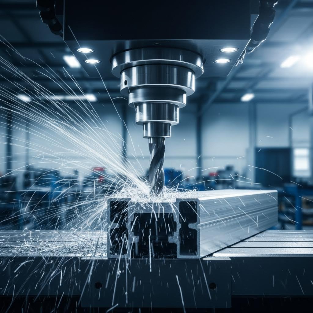
CNC aluminum extrusion machining is a manufacturing process where Computer Numerical Control machines perform precision cutting, drilling, milling, and shaping operations on aluminum extrusion profiles to create finished components with tight tolerances and complex features.
This hybrid approach leverages the best of both worlds. You start with an extruded aluminum profile - a near-net-shape piece already formed close to your final dimensions - then refine it through automated CNC operations to achieve exact specifications.
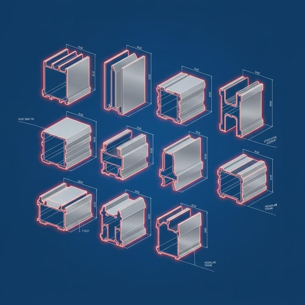
The journey begins with aluminum extrusion, a hot-forming process where a heated aluminum billet gets pushed through a custom-shaped steel die. Imagine squeezing toothpaste through a shaped nozzle - the aluminum emerges with a consistent cross-sectional shape, whether that's a simple tube, an intricate heat sink fin pattern, or a complex architectural profile.
But here's the limitation: extrusion can only produce parts with uniform cross-sections along their length. It cannot create holes, threads, angled cuts, or varying features along the profile. That's where CNC machining enters the picture.
CNC machines use programmed computer software to control cutting tools that remove material with exceptional precision. When applied to aluminum extrusions, these machines can add:
So what is CNC aluminium processing actually accomplishing? It bridges the gap between basic extruded shapes and fully functional components ready for assembly. According to industry standards, tolerances as tight as ±0.08 mm are achievable through this combined approach - precision that extrusion alone simply cannot deliver.
The value proposition becomes clear when you compare alternatives. Machining a complex part entirely from solid aluminum billet wastes significant material and requires extensive cutting time. Aluminium extrusion machining, however, starts with a profile already shaped close to the final form. The CNC operations only remove material where additional precision or features are necessary.
This near-net-shape starting point delivers three key advantages:
For modern manufacturers across automotive, aerospace, electronics, and architectural sectors, CNC aluminium extrusion represents an optimized production pathway. It combines the efficient forming capability of extrusion with the precision finishing power of computer-controlled machining - enabling one-stop manufacturing from conceptual design to finished aluminum components.
Now that you understand what extrusion machining accomplishes, let's explore exactly how it happens. Each CNC operation serves a specific purpose in transforming raw aluminum profiles into functional components. Whether you're designing parts for industrial equipment or architectural applications, knowing these processes helps you communicate effectively with manufacturers and optimize your designs.
A CNC machine for aluminum extrusions can perform multiple operations in a single setup, dramatically reducing handling time and improving dimensional accuracy between features. Modern facilities often utilize work envelopes capable of handling profiles up to 144 inches for standard CNC operations, with laser cutting systems extending that capacity to 288 inches for longer architectural or industrial applications.
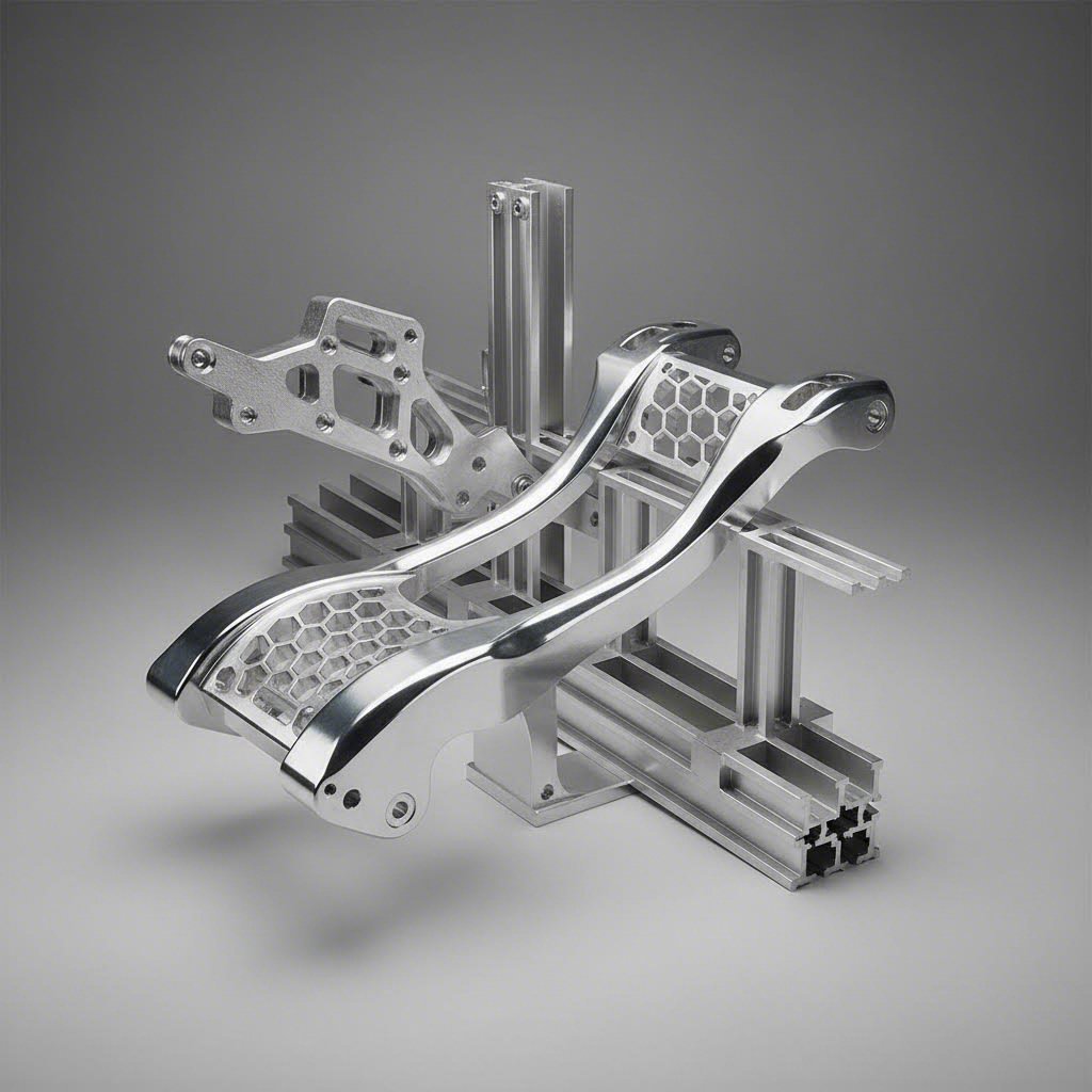
Milling uses rotating cutting tools to remove material from the extrusion surface, creating flat faces, pockets, slots, and complex three-dimensional contours. Think of it as sculpting - the rotating cutter carves away aluminum to reveal your intended shape.
The profile milling machine capabilities most commonly applied to aluminum extrusions include:
Aluminum's excellent machinability makes it particularly suited for milling operations. The material chips easily and cleanly, allowing higher cutting speeds than steel while producing superior surface finishes. This characteristic means faster production cycles and lower tooling costs - benefits that directly impact your project economics.
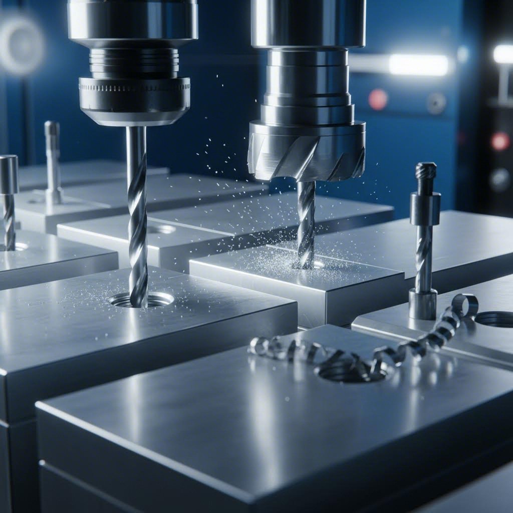
Virtually every machined aluminum extrusion requires holes. Whether you're mounting electronics, joining structural members, or integrating hardware, drilling and tapping operations create the connection points that transform individual profiles into assembled systems.
Understanding how to cut aluminum extrusions for assembly starts with knowing the hole types available:
Tapping extends drilling functionality by cutting internal threads into drilled holes. This eliminates the need for separate nuts, reducing part count and simplifying assembly. Common thread types include:
The precision of CNC drilling ensures hole patterns align perfectly across multiple profiles, critical when components must bolt together without binding or misalignment. According to Precision Steel Services, modern 5-axis CNC equipment can maintain tight tolerances even on complex parts, expediting fabrication without increasing costs.
Before extrusions can be assembled, they need precise end treatments. Raw extrusions arrive in mill lengths and require cutting to exact dimensions, often with specific angle cuts or notch patterns for joinery.
The cutting and finishing operations commonly performed on aluminum extrusions include:
End finishing often includes deburring operations that remove sharp edges left by cutting tools. This step improves safety during handling and assembly while enhancing the professional appearance of finished components.
| Operation Type | Primary Function | Typical Applications |
|---|---|---|
| Face Milling | Creates flat mounting surfaces | Motor mounts, sensor brackets, assembly interfaces |
| Pocket Milling | Removes material for recesses | Weight reduction, wire channels, component housing |
| Drilling/Counterboring | Creates fastener holes | Bolt patterns, pin locations, access holes |
| Tapping | Adds internal threads | Screw mounting, adjustable hardware, assembly points |
| Miter Cutting | Angles profile ends | Frame corners, architectural trim, structural joints |
| Notching | Creates interlocking cutouts | Profile intersections, clearance cuts, decorative details |
Each process builds upon the others to transform a basic aluminum extrusion into a fully functional component. The key advantage of working with a capable machining partner lies in their ability to combine these operations efficiently, often completing multiple features in a single machine setup. This integrated approach minimizes handling, maintains tighter tolerances between features, and reduces overall production time.
With these fundamental processes understood, the next critical decision involves selecting the right aluminum alloy for your specific machining requirements.
Choosing the right aluminum alloy before machining begins might be the most consequential decision you'll make. Why? Because alloy composition directly impacts cutting speeds, tool life, surface finish quality, and ultimately - your project budget. Yet many manufacturers overlook this critical step, treating all aluminum as interchangeable.
The truth is, aluminum CNC machining outcomes vary dramatically based on alloy selection. A profile machined from 6063 behaves entirely differently under the cutting tool than one made from 7075. Understanding these differences helps you specify the right material from the start, avoiding costly compromises later.
When machining aluminum parts for different applications, the alloy choice often comes down to two primary categories: architectural and industrial grades. Each serves distinct purposes based on their inherent properties.
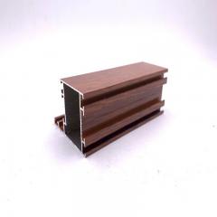
Architectural aluminum (6063) dominates window frames, curtain walls, door systems, and decorative trim. According to Dajin Precision, 6063 holds a better surface finish for decorative parts than 6061 and other 6xxx alloys. This makes it the go-to choice when aesthetics matter as much as function. The alloy's composition (nominally 0.7% Mg, 0.4% Si, and 98.9% Al) produces smooth, consistent surfaces that anodize beautifully.
What makes 6063 particularly appealing for architectural work?
Structural aluminum (6061) takes over when strength requirements increase. This workhorse alloy appears in truck wheels, bicycle frames, marine hardware, aircraft structures, and countless industrial applications. The higher silicon and magnesium content (0.6% Si, 1.0% Mg) delivers greater yield strength and fatigue resistance than architectural grades.
6061 aluminum is better machined than 6063 aluminum in CNC turning, milling, and die casting operations. When cyclical loading is common - such as in aircraft and marine environments - 6061's higher bearing strength makes it the preferred choice for aluminium machined parts that must withstand repeated stress.
Beyond the architectural versus structural divide, alloy selection profoundly affects what happens at the cutting tool interface. Different aluminum compositions respond uniquely to machining operations, influencing everything from chip formation to achievable tolerances.
Ceratizit's machining research divides aluminum wrought alloys into three machinability classes. Softer alloys like 6063 in unhardened states tend toward "smearing effects" with stronger built-up edge formation. Harder alloys in the 6000 and 7000 series, with tensile strengths between 300-600 N/mm², show reduced built-up edge formation and cleaner chip evacuation.
Here's what this means practically for your machining line with light alloys:
| Alloy | Machinability Rating | Typical Applications | Surface Finish Quality | Strength Characteristics | Recommended Use Cases |
|---|---|---|---|---|---|
| 6063 | Good (requires cutting fluid) | Window frames, architectural trim, decorative profiles | Excellent - superior anodizing response | Moderate (lower than 6061) | Aesthetic applications, complex extrusions, architectural components |
| 6061 | Excellent | Structural frames, marine hardware, automotive chassis | Very Good | Good yield and fatigue strength | General structural work, prototypes, parts requiring welding |
| 7075 | Moderate (causes tool wear) | Aircraft structures, military equipment, sports equipment | Good (with proper tooling) | Very High - rivals steel | High-stress aerospace parts, applications where strength-to-weight is critical |
| 2024 | Challenging (work hardens) | Aircraft wings, fuselage structures, military vehicles | Good (requires sharp tooling) | High - excellent fatigue resistance | Aerospace load-bearing components, parts under cyclic stress |
When does the increased machining difficulty of high-strength alloys like 7075 justify the extra effort? According to First Mold's analysis, 7075 aluminum becomes the right choice when applications need high strength and low weight, or when parts will be exposed to significant heat and friction. The aerospace industry relies heavily on 7075 for aircraft wings, fuselage structures, and military tooling where failure isn't an option.
However, 7075's reduced corrosion resistance compared to 6061 means additional surface treatment may be necessary for exposed applications. The alloy also costs more and requires premium cutting tools with controlled speeds to manage the accelerated wear its hardness creates.
For 2024 aluminum, the challenge intensifies further. This alloy occasionally undergoes work hardening during machining, requiring proper lubrication and cooling to prevent overheating. Using sharp tools and managing cutting speed becomes vital to overcome tool wear. Yet for aerospace parts experiencing significant periodic stress, 2024's superior fatigue resistance makes the machining investment worthwhile.
The bottom line? Match your alloy to your application requirements first, then adjust your machining parameters accordingly. A part that needs to look beautiful on a building facade calls for 6063. A structural bracket facing repeated loading demands 6061. And when lives depend on maximum strength at minimum weight, 7075 or 2024 justify their machining challenges.
With the right alloy selected, your next consideration becomes equally important: how does the extrusion's profile design affect your machining strategy?
Imagine spending hours programming the perfect toolpath, only to watch your machined aluminum extrusion warp the moment it's unclamped. Frustrating, right? This scenario happens more often than you'd expect - and it almost always traces back to decisions made long before the CNC machine ever powered up.
The extrusion profile you specify directly determines how successfully that part will machine. Wall thickness, internal structure placement, and overall geometry create the foundation for every downstream operation. When designers understand this connection, they create aluminum profile CNC parts that machine faster, hold tighter tolerances, and cost less to produce.
According to American Douglas Metals, raw material costs constitute 90% of basic extrusion expenses. That means profile optimization isn't just about machining efficiency - it's about maximizing the value of every pound of aluminum you purchase.
Wall thickness might seem like a simple specification, but it creates ripple effects throughout your entire machining operation. Get it wrong, and you'll battle distortion, chatter, and dimensional instability from the first cut to the last.
Here's the core challenge: thin walls flex under cutting forces. When a milling cutter engages a wall that's too thin relative to its height, the wall deflects away from the tool. This creates undersized cuts in some areas and oversized cuts in others. The part might measure correctly when clamped, but spring back to an incorrect shape once released.
Research from Frigate's engineering team reveals that up to 25% of production delays in high-precision aluminum parts stem from warping-related failures. Much of this traces directly to wall thickness decisions made during initial design.
Key wall thickness guidelines for extruded aluminum CNC applications:
Large differences between adjacent wall thicknesses create uneven conditions during both extrusion and subsequent machining. The thick sections retain heat longer, cool at different rates, and respond differently to cutting forces than their thinner neighbors. This mismatch produces internal stresses that may not appear until hours or days after machining - a phenomenon called delayed warping.
Ever tried holding a round tube while drilling a hole through its side? The part wants to roll, spin, and generally refuse to stay put. Now imagine that challenge multiplied across hundreds of production parts. Fixturing strategy often determines whether a cnc alu profile machines profitably or becomes a money-losing nightmare.
Thoughtful extrusion design builds fixturing solutions directly into the profile geometry. When you include clamping surfaces, registration features, and stable bases during the extrusion design phase, you eliminate the need for expensive custom fixtures later.
Design features that simplify workholding:
Hollow versus solid profiles present distinctly different fixturing challenges. Solid extrusions offer simple, stable clamping surfaces but generate more machining waste when removing material. Hollow profiles reduce weight and material cost but require internal support during heavy cutting operations to prevent collapse or distortion.
According to industry best practices, designing internal features like cooling channels or bolt pathways directly into the hollow profile saves both material and machining time - you're essentially getting two operations for the price of one.
Internal webs, ribs, and channels add structural strength to aluminum extrusions. But poorly positioned internal features create machining headaches that slow production and compromise quality.
Consider drilling operations through hollow profiles. The drill enters the first wall cleanly, but what happens when it breaks through into an internal cavity? Without proper support, the exit wall can deflect, creating oversized or egg-shaped holes. When the drill then engages the opposite wall, it may grab or chatter against the unsupported material.
Strategic internal web placement solves these problems:
Chip evacuation deserves special attention for enclosed or semi-enclosed profiles. Aluminum produces long, stringy chips that love to wrap around tooling and pack into tight spaces. When chips have nowhere to go, they re-cut and damage the surface finish, generate excessive heat, and can even break tools.
Solutions include designing chip clearance channels into the profile, using through-coolant tooling that flushes chips from enclosed areas, and planning toolpaths that allow chip extraction between cuts.
Aluminum machines fast - sometimes too fast for its own good. High-speed cutting generates significant heat, and aluminum's excellent thermal conductivity spreads that heat rapidly through the workpiece. Uneven heating causes uneven expansion, and uneven expansion causes dimensional errors.
Profile design influences thermal behavior in ways many engineers overlook:
Frigate's research confirms that advanced thermal load control - including high-flow coolant systems and optimized toolpaths that avoid heat concentration - significantly reduces warping in aluminum extrusion machining. But the profile design itself determines how effectively these strategies work.
The most thermally stable profiles share common characteristics: relatively uniform wall thickness, symmetrical mass distribution, and geometry that allows coolant access to all cutting zones. When these principles guide your extrusion design, the CNC operations that follow become predictable and repeatable.
Thoughtful profile design ultimately saves money at every step. You'll see faster cycle times because proper wall thickness eliminates chatter and allows aggressive cutting parameters. You'll experience fewer rejected parts because fixturing stability ensures consistent positioning. And you'll achieve tighter tolerances because thermal management keeps dimensional drift under control.
With profile design optimized for machining success, the next critical factor becomes selecting the right cutting parameters and tooling to maximize aluminum's excellent machinability.
Ever watched aluminum chips fuse into a gummy mess on your end mill? Or heard that sickening snap of a broken cutter flying across the shop? These frustrations usually trace back to one problem: treating aluminum like it's just softer steel. It isn't. Aluminium CNC milling demands its own approach to speeds, feeds, and tooling - get these right, and the material practically machines itself.
According to CNC Solutions, aluminum requires less cutting force than harder materials like steel, but its lower melting point creates a unique challenge. Loose chips can overheat and fuse directly to the tool, dulling the cutting edge and triggering a cascade of heat buildup that leads to premature tool failure.
Understanding how to cut aluminum extrusions properly means mastering three interconnected variables: spindle speed, feed rate, and depth of cut. Balance these correctly, and you'll produce CNC machined aluminum parts with excellent surface finish and minimal tool wear.
Here's something that surprises many machinists: aluminum's recommended cutting speed of 300-600 meters per minute (using carbide tooling) rivals that of wood. But unlike woodworking, the optimal feeds and speeds for aluminum fall within a much tighter range. Stray outside that window, and problems multiply quickly.
The relationship works like this:
The critical mistake? Combining high spindle RPMs with feed rates that are too slow. When this happens, the tool spends more time rubbing against the aluminum than actually cutting it. This friction generates excessive heat, dramatically reducing tool life and creating the built-up edge that ruins surface finish.
Conversely, pushing feed rates too high without adequate chip evacuation leads to packed flutes, re-cutting of chips, and the familiar sound of a broken tool hitting the wall behind you.
For CNC projects in aluminum, aim to maintain a consistent chip thickness that produces short, shiny curls flying cleanly out of the cut. According to Star Tool USA, if your chips are long, stringy, and stuck to the cutting edge, you're fighting built-up edge and heading toward a smeared finish.
Choosing the right cutting tool for aluminum centers on one overriding principle: maximize chip evacuation space. Every decision about flute count, helix angle, and coating should support this goal.
Unlike steel machining where four or more flutes often work best, aluminum rewards fewer flutes with larger gullets:
Here's a practical test from industry experts: run a short trial with a 2-flute for slotting and a 3-flute for side milling, then compare spindle load and surface quality. The results will guide your standardization decisions.
Aluminum rewards higher helix angles because a steep helix shears more cleanly and pulls chips up and out of the cut:
High-Speed Steel simply isn't strong enough under the cutting conditions aluminum demands. According to CNC machining specialists, aluminum's relative softness means you should prioritize tool hardness over toughness. A harder tool material keeps the cutting edge sharp longer, creating better finishes and reducing the aluminum deposits that dull lesser tools.
Always use carbide end mills for aluminum extrusion machining. The higher speeds and sharper-for-longer edges create greater shearing force, reducing that long, stringy swarf that fouls cutters.
Here's where aluminum machining differs most dramatically from steel work. Those gold TiN-coated end mills that look so professional? Skip them for aluminum. According to CNC training experts, TiN coating is designed for wear resistance when machining more abrasive materials - it's actually rougher and more chemically reactive with aluminum than an uncoated tool. The same applies to TiAlN, TiCN, and AlTiN coatings.
Recommended coatings for aluminum:
A simple field test when finishes go wrong: swap your coated tool for a polished uncoated version on a finish pass. If the surface improves immediately, your coating choice was mismatched to the material.
Chip evacuation becomes the deciding factor in many aluminum operations. Coolant isn't just about temperature control - it's about flushing chips away before they can re-cut, pack into corners, or weld onto the tool.
When chips start to bird-nest or the machined surface goes matte, prioritize chip evacuation first. More coolant volume, better aim into the cut, and a verified sharp edge will usually solve finish problems before you need to rewrite programs or buy new tools.
The bottom line for aluminum extrusion machining: use fewer flutes than you'd choose for steel, run higher speeds with appropriate feeds, select coatings that repel rather than attract aluminum, and never let chips accumulate in the cutting zone. Master these fundamentals, and your CNC machined aluminum parts will consistently meet specifications while your tooling costs stay under control.
With cutting parameters and tooling optimized, the next consideration becomes matching your machine configuration to part complexity - when does basic 3-axis work suffice, and when do you need advanced multi-axis capabilities?
Picture this: you've designed an aluminum extrusion bracket with mounting holes on three different faces, each at compound angles. Your 3-axis machine can technically reach every feature - but only after five separate setups, each introducing positioning errors that stack up against your tolerance budget. Sound familiar?
The number of axes your CNC machine controls fundamentally shapes what's possible, practical, and profitable. According to WeNext's machining analysis, choosing between 3-axis, 4-axis, and 5-axis configurations depends on material, production volume, budget, and geometric complexity. Understanding when each configuration makes sense helps you avoid both underspending on capability and overspending on equipment you don't need.
Most aluminum extrusion CNC work starts with 3-axis machines - and for good reason. These workhorses move the cutting tool along X, Y, and Z coordinates, handling flat surfaces, drilled holes, and simple profiles with excellent efficiency. If your extrusion only requires machining on one or two faces, 3-axis delivers the best cost-to-capability ratio.
But here's where limitations emerge: 3-axis machines can only approach the workpiece from one direction per setup. Need to drill holes on the top and side of your profile? That's two setups. Add angled features or undercuts? You're looking at custom fixtures, creative workholding, or features that simply can't be reached.
The jump to 4-axis adds rotation around the X-axis (the A-axis), allowing the workpiece to rotate during machining. According to industry research, this seemingly simple addition eliminates fixture changes when machining two sides of a part. More importantly, it maintains tight tolerances between features on different sides because the loss of dimensional accuracy from mounting and resetting is eliminated.
5-axis machining takes this further by adding a second rotational axis. The cutting tool can now approach the workpiece from virtually any angle, accessing complex surfaces and multiple sides in a single setup. For precision aluminum extrusion work involving compound angles, deep cavities, or aerodynamic contours, this capability transforms what's achievable.
| Configuration | Typical Applications | Complexity Level | Cost Implications | Ideal Use Cases |
|---|---|---|---|---|
| Single-Spindle 3-Axis | Flat profiles, simple drilling, face milling, basic pockets | Low - straightforward programming | Lowest equipment and operating costs | High-volume 2D work, signage, simple structural profiles |
| Dual-Spindle 3-Axis | Same as single-spindle with doubled throughput | Low to Moderate | Higher capital, lower per-part cost at volume | Production runs requiring maximum output on simple geometries |
| 4-Axis (3+1) | Multi-sided profiles, rotary indexing, cylindrical features | Moderate - rotary positioning adds setup considerations | Moderate - often eliminates fixture costs | Parts requiring features on 2-4 sides, curved furniture components |
| 5-Axis Indexed (3+2) | Compound angles, deep cavities, multi-surface machining | Moderate to High - requires advanced CAM | Higher equipment cost, reduced setup time | Aerospace brackets, complex architectural details, mold components |
| 5-Axis Simultaneous | Freeform surfaces, turbine blades, sculptured contours | High - demands specialized programming expertise | Highest - nearly twice 3-axis machine cost | Aerospace structures, medical implants, forming tools |
So when does aluminium CNC machining genuinely require 5-axis capability? The answer often comes down to three scenarios: compound angles, undercuts, and surface continuity requirements.
Compound angles present the clearest case. When your aluminum profile needs a hole drilled at 30 degrees off vertical and 15 degrees off horizontal simultaneously, a 3-axis machine simply cannot position the tool correctly. You'd need an angled fixture - expensive, time-consuming to set up, and limited to that single angle combination.
Undercuts and hidden features create similar challenges. Imagine machining a dovetail slot on the underside of an extrusion flange. The tool must approach from below and at an angle - impossible for a vertically-oriented 3-axis spindle. According to Frigate's engineering team, 5-axis machines can create complex freeform surfaces, undercuts, and deep cavities that would be either impossible or very time-consuming with traditional setups.
Surface finish continuity matters for aerospace and architectural applications where visible machining marks must flow smoothly across contoured surfaces. 5-axis simultaneous machining keeps the tool perpendicular to the surface throughout the cut, eliminating the scalloped appearance that indexed operations leave behind.
However, not every complex part demands full 5-axis capability. Industry experts note that indexed 3+2 axis machining allows the use of shorter, more rigid cutting tools. These tools can be tilted toward the workpiece surface for faster feeds and speeds, meaning 3+2 machining often produces parts faster than full 5-axis for geometries that don't require continuous surface sculpting.
If you're a hobbyist or small-batch manufacturer, the multi-axis question takes on different dimensions. Desktop 3-axis routers and mills handle many aluminum extrusion modifications capably - drilling mounting holes, cutting profiles to length, milling simple pockets. The learning curve remains manageable, and equipment costs stay within reach.
But consider this scenario: you need ten prototype brackets with compound-angle mounting holes. Your 3-axis setup requires three custom fixtures at $200 each, plus four hours of setup time per fixture. Total: $600 in fixtures plus twelve hours before cutting even begins.
A professional 5-axis service machines all ten parts in a single setup, delivering finished pieces in days rather than weeks. The per-part cost may be higher, but the total project cost - including your time - often favors outsourcing.
Ask yourself these questions when deciding:
According to CNC World's analysis, 5-axis routers are significantly more expensive - requiring skilled operators, specialized CAM software, and more training than 3-axis equipment. The best router is the one that meets your needs without adding unnecessary complexity.
For aluminum extrusion work specifically, many manufacturers find 4-axis capability hits the sweet spot. The rotary axis handles multi-sided profiles elegantly, and equipment costs remain substantially below full 5-axis systems. Reserve 5-axis services for parts where compound angles and sculptured surfaces genuinely demand simultaneous multi-axis motion.
With your machining configuration matched to part complexity, the next critical factor becomes understanding what precision tolerances and surface finishes you can realistically achieve - and how these specifications affect your downstream finishing operations.
You've selected the right alloy, optimized your profile design, and dialed in cutting parameters. But here's the question that ultimately determines whether your parts function correctly: what tolerances can you actually hold, and how smooth will those machined surfaces be?
Tolerance and surface finish specifications often get overlooked until inspection day arrives. Then suddenly, a part that looked perfect under shop lighting gets rejected because the Ra value exceeds specification or a critical dimension drifted outside acceptable limits. Understanding what's achievable - and what factors influence these outcomes - prevents costly surprises and rejected batches.
Tolerance capability in custom aluminum machining depends on multiple interacting factors: machine rigidity, tool condition, thermal stability, and the profile geometry itself. Knowing where your process falls on the tolerance spectrum helps you specify requirements that are both achievable and appropriate for your application.
Standard machining tolerances for machined aluminium typically fall within ±0.005 inch (±0.127 mm). This level suits most industrial applications where parts must fit together but don't require interference fits or precision alignment. Think structural brackets, general enclosures, and non-critical mounting features.
Precision tolerances tighten to ±0.001 inch (±0.025 mm) or better for demanding applications. Achieving these numbers requires careful attention to every variable: temperature-controlled environments, premium tooling, frequent measurement verification, and machine tools with proven repeatability.
Here's a practical breakdown of tolerance grades and their typical applications:
What factors push tolerances wider than you'd like? Thin-wall profiles deflect under cutting forces. Long, slender extrusions flex and vibrate. Thermal expansion during high-speed machining shifts dimensions mid-cut. And worn tooling produces increasingly variable results until someone notices the drift.
The machining line for aluminium parts that consistently hits tight tolerances addresses each variable systematically: rigid fixturing that prevents deflection, sharp tooling changed before wear becomes problematic, coolant strategies that maintain thermal equilibrium, and in-process measurement that catches drift before it compounds.
Surface roughness describes the microscopic texture left by machining operations - those tiny peaks and valleys created as the cutting tool repeatedly engages and removes material. According to Geomiq's comprehensive surface roughness guide, these deviations affect not only aesthetics but functionality and durability in various applications.
The most common measurement is Ra (Roughness Average), expressed in micrometers (µm). Lower Ra values indicate smoother surfaces with less variation between peaks and valleys. Here's what different Ra levels look like in practice:
Different machining operations produce characteristically different surface textures. Face milling leaves a distinctive pattern of circular arcs. End milling creates parallel lines following the tool path. Turning produces concentric rings. Each texture behaves differently under load, against mating surfaces, and through subsequent finishing operations.
According to industry research, achieving smoother finishes costs more - not just in machining time, but in the precision required throughout the process. Moving from 3.2 µm Ra to 1.6 µm Ra adds approximately 2.5% to production costs. Reaching 0.8 µm Ra increases costs by about 5%. And achieving 0.4 µm Ra - requiring polishing beyond machining - can add 15% or more to baseline production costs.
Here's something many engineers discover too late: the surface finish leaving your CNC machine directly impacts how your parts look after anodizing, powder coating, or other treatments. Poor machining marks don't disappear under a coating - they show through, sometimes more prominently than before.
Anodizing amplifies surface texture because the electrochemical process builds oxide layers that follow the existing topography. A machined surface at 3.2 µm Ra may appear acceptable before anodizing, then reveal every tool mark after the bright, reflective oxide layer forms. For architectural or consumer-facing parts, plan for 1.6 µm Ra or finer before anodizing if appearance matters.
Powder coating has some ability to fill minor surface imperfections, but deep machining marks, scratches, or pitting telegraph through the coating layer. Parts destined for powder coating benefit from either smooth machining or intermediate bead blasting to create a uniform matte texture that hides variations.
Functional surfaces demand appropriate finish specifications regardless of appearance:
The takeaway? Specify surface finish requirements based on function and downstream processing, not just what looks acceptable on the machine. A few extra seconds per part achieving proper finish quality prevents rejected batches after expensive coating operations.
With tolerances and surface finish specifications understood, the next consideration becomes how these technical requirements translate across different industry applications - where aerospace precision differs dramatically from architectural aesthetics.
What tolerance does an aircraft wing spar demand compared to a window frame? The answer might surprise you - sometimes they're identical, but the path to achieving those specifications couldn't be more different. Each industry brings unique priorities that fundamentally shape how aluminum extrusions get machined, inspected, and delivered.
Understanding these sector-specific requirements helps you communicate effectively with machining partners and set realistic expectations for your projects. Whether you're designing components for an aluminium extrusion machine, specifying parts for an aluminum extrusion line, or developing aluminium airfoil extrusion profiles, knowing what your industry demands ensures specifications match actual needs.
When lives depend on every component performing flawlessly at 40,000 feet, aerospace machining operates under constraints that would seem excessive in other sectors. Tight tolerances represent just the starting point - material traceability, process documentation, and inspection protocols add layers of complexity that directly impact machining strategy.
Aerospace aluminum extrusion machining typically demands:
High-strength alloys like 7075 and 2024 dominate aerospace applications precisely because their strength-to-weight ratios justify the machining challenges they present. Aircraft structures, wing components, and fuselage frames demand materials that rival steel's strength at a fraction of the weight.
What makes aerospace machining particularly demanding? The inspection burden. According to industry standards, surface roughness inspection results should be documented and linked to specific parts, processes, and production batches to ensure complete traceability. Every machined feature gets measured, documented, and verified against engineering specifications before parts leave the shop.
Dimensional accuracy checks using CMM equipment verify that all critical dimensions meet drawing specifications. Material certification verification confirms alloy grade, temper, and lot traceability for each aluminum batch. Visual and defect inspection identifies surface flaws, tool marks, or machining defects before final delivery.
Automotive manufacturing flips the priority equation. While aerospace obsesses over individual part perfection, automotive focuses on producing thousands of consistent parts per shift. Cycle time, repeatability, and cost-per-piece drive every machining decision.
Sounds like quality takes a back seat? Not exactly. Automotive tolerances remain demanding - typically ±0.002 to ±0.005 inch for critical assembly interfaces. But the emphasis shifts toward process stability rather than individual part inspection. If your process is capable and controlled, the parts will be correct.
Key considerations for automotive aluminum extrusion machining:
Alloy selection in automotive applications balances machinability against performance requirements. 6061-T6 dominates structural applications - chassis components, suspension brackets, and engine mounts - because it machines efficiently while delivering adequate strength. Where weight savings justify additional cost, 7075 appears in performance and racing applications.
Process stability becomes paramount when surface roughness deviations can result from tool wear, improper cutting parameters, unstable fixturing, or material inconsistencies. Inconsistent surface finish across production batches often indicates process variation rather than isolated defects. Automotive quality systems demand corrective actions that address root causes - adjusting machining parameters, replacing worn tools on schedule, and improving fixturing stability rather than sorting good parts from bad.
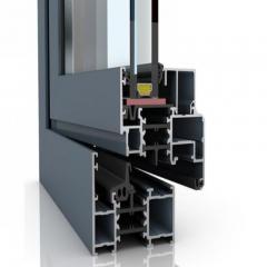
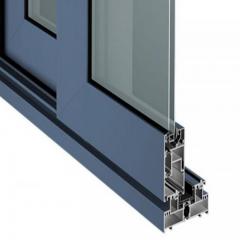
Walk into any modern commercial building, and you're surrounded by machined aluminum extrusions. Curtain wall frames, door hardware, handrail brackets, decorative trim - architectural applications prioritize visual perfection and seamless integration over extreme dimensional precision.
Architectural machining requirements center on:
The 6063 alloy dominates architectural work because it extrudes into complex decorative profiles and accepts anodizing beautifully. Its slightly lower strength compared to 6061 rarely matters for facade applications where wind loads and thermal movement govern design rather than structural stress.
Here's where architectural machining differs most from industrial work: the finish is the function. A structural bracket hidden inside a machine enclosure can carry tool marks without consequence. A visible curtain wall component with the same marks represents a quality failure, regardless of dimensional accuracy.
According to surface finish research, different aluminum alloys exhibit varying surface finish behavior due to differences in hardness, microstructure, and machinability. Post-machining processes such as anodizing, polishing, or blasting further modify surface texture and must be considered when defining inspection criteria. For architectural applications, specifying Ra 1.6 µm or finer before anodizing prevents machining marks from telegraphing through the finished coating.
Between aerospace precision and architectural aesthetics lies a broad category of appliance and consumer applications. Refrigerator handles, laptop enclosures, audio equipment housings, and fitness equipment frames all require machined aluminum extrusions with balanced specifications.
This sector typically prioritizes:
Understanding your end-use application guides every upstream decision. Specifying aerospace-grade tolerances for architectural components wastes money without improving performance. Accepting automotive surface finishes on premium consumer electronics creates disappointed customers.
Consider this decision framework when defining machining requirements:
| Industry Sector | Typical Tolerance | Surface Finish Priority | Key Machining Drivers | Common Alloys |
|---|---|---|---|---|
| Aerospace | ±0.001 inch | Functional integrity, fatigue resistance | Documentation, traceability, inspection | 7075, 2024, 6061 |
| Automotive | ±0.002-0.005 inch | Process consistency, functional surfaces | Cycle time, repeatability, cost per piece | 6061, 6063 |
| Architectural | ±0.005 inch | Visual perfection, coating compatibility | Surface quality, assembly fit, aesthetics | 6063, 6061 |
| Appliance/Consumer | ±0.005-0.010 inch | Visible surface quality, cost balance | Price optimization, appearance, assembly | 6063, 6061 |
The most successful machining projects begin with honest conversations about what actually matters. Does your application genuinely require ±0.001 inch tolerances, or would ±0.005 inch serve equally well at lower cost? Must every surface achieve 0.8 µm Ra, or can hidden areas accept standard 3.2 µm finishes?
Overly tight roughness requirements increase machining cost and inspection complexity without necessarily improving performance. The key lies in matching specifications to genuine functional requirements - saving precision budget for features that truly demand it while accepting appropriate tolerances elsewhere.
With industry requirements clearly understood, the final consideration becomes selecting a machining partner capable of meeting your specific sector's demands while providing the integrated services that streamline your supply chain.
You've specified the perfect alloy, optimized your profile design, and defined precise tolerances. But here's the reality check: none of that matters if your machining partner can't deliver. Choosing the wrong aluminum machining services provider leads to missed deadlines, out-of-spec parts, and frustrating rework cycles that drain your budget and patience.
According to TMCO's fabrication expertise, selecting the right aluminum fabricator involves more than just comparing quotes. The best partner offers technical expertise, advanced equipment, proven processes, and open communication. These factors directly impact whether your precision aluminum machining project succeeds or struggles.
So what separates capable CNC aluminum fabrication partners from those who'll leave you scrambling? Let's break down the evaluation criteria that actually predict success.
Equipment tells a story. A shop running aging 3-axis machines with limited work envelopes simply cannot deliver the same results as one equipped with modern multi-axis CNC centers. But equipment alone doesn't guarantee quality - how that equipment is applied matters equally.
When evaluating a potential cnc bewerking partner, examine these technical factors:
Here's a telling question: ask potential partners about their fixture development process. According to industry research, fixture and toolpath know-how is the real separator. Anyone can buy a machine; few can make it behave. If a supplier has handled 0.020-inch walls or long, skinny pockets without turning them into tuning forks, that's a good sign of genuine capability.
Raw machined aluminum rarely ships directly to end users. Anodizing, powder coating, and specialty finishes transform machined parts into finished products. But here's where supply chains often fragment - one vendor extrudes, another machines, a third anodizes, and a fourth powder coats. Each handoff introduces delays, quality variations, and finger-pointing when something goes wrong.
Evaluate surface treatment capabilities as part of your partner selection:
According to fabrication experts, finishing processes such as anodizing, powder coating, and polishing protect aluminum parts from wear and environmental damage, ensuring both performance and longevity. Partners offering these services in-house eliminate handoff delays and maintain quality control throughout the production sequence.
Imagine this scenario: your extrusion supplier delivers profiles with wall thickness at the high end of tolerance. Your machining partner, expecting nominal dimensions, runs their programmed toolpaths. The result? Features positioned incorrectly relative to profile walls, rejected parts, and urgent phone calls.
This coordination failure happens constantly when extrusion and machining operate as separate, disconnected operations. Integrated partners eliminate this gap by controlling both processes under unified quality systems.
The benefits of working with an integrated extrusion and machining partner include:
For manufacturers seeking this integrated approach, Shengxin Aluminium's deep processing services exemplify the single-source model. With 35 extrusion presses ranging from 600T to 5500T capacity, state-of-the-art CNC machining centers for precise cutting, drilling, and bending, plus comprehensive surface treatments including anodizing, powder coating, PVDF, and micro-arc oxidation, the facility provides end-to-end capability under unified quality control.
What makes this integration particularly valuable? Technical support flows from die development through mass production. Engineers who design the extrusion die understand exactly how that profile will be fixtured and machined. This knowledge loop prevents the design-manufacturing disconnects that plague fragmented supply chains.
Certifications demonstrate commitment to documented, repeatable processes. But framed certificates on the wall mean nothing if daily operations ignore the systems they represent.
According to industry guidance, look for ISO-certified or AS9100-compliant manufacturers who follow documented inspection and testing processes. These certifications matter, but what matters more is whether the shop actually follows them, not just frames them for auditors.
When evaluating quality systems, ask specific questions:
The best precision aluminum machining partner doesn't just execute your drawings - they improve them. Design for manufacturability feedback early in development prevents expensive discoveries during production.
According to DFM specialists, a supplier who understands aluminum will warn you early about thin walls that will vibrate, pockets that may trap chips, surfaces likely to warp after finishing, and places where tolerances stack up poorly. Clear communication prevents wrong assumptions, which are responsible for a surprising number of expensive failures.
Evaluate communication practices before committing:
The lowest quote rarely represents the lowest total cost. According to industry experience, hidden costs usually show up later: batches rejected during incoming inspection, emergency re-machining, assemblies delayed because holes don't line up, and entire projects derailed because parts moved after anodizing.
A strong aluminum machining services partner saves money in ways that don't appear on a basic quote sheet: higher yields, fewer surprises, and better timelines. When evaluating potential partners, weight these factors alongside price:
| Evaluation Criterion | What to Look For | Red Flags |
|---|---|---|
| Technical Capability | Modern multi-axis CNC, diverse press tonnage, in-house inspection | Aging equipment, outsourced inspection, limited work envelope |
| Integration Level | Extrusion, machining, and finishing under one roof | Multiple handoffs between separate vendors |
| Quality Systems | Active certifications, documented procedures, traceable materials | Certifications but no evidence of daily compliance |
| Surface Treatments | Anodizing, powder coating, PVDF, specialty options in-house | All finishing outsourced to third parties |
| Technical Support | DFM feedback, engineering access, proactive communication | Quote-only responses, no design input offered |
| Scalability | Prototype to production using consistent processes | Different approaches for low versus high volume |
Your CNC aluminum extrusion machining project deserves a partner who brings genuine capability, integrated services, and technical expertise to every order. Whether you're producing aerospace components demanding ±0.001-inch tolerances or architectural profiles requiring flawless anodized finishes, the right partner transforms specifications on paper into quality parts in your hands.
For manufacturers exploring integrated extrusion and deep processing solutions, Shengxin Aluminium's comprehensive capabilities provide the single-source accountability that eliminates supply chain fragmentation. With over 30 years of industry experience and technical support spanning die development through mass production, the facility represents the integrated model that simplifies complex aluminum projects.
For optimal results cutting aluminum extrusions, use 2-3 flute carbide end mills with high helix angles (35-45 degrees). Avoid TiN-coated tools as they can cause aluminum adhesion. Instead, choose uncoated polished carbide, ZrN, or DLC (Diamond-Like Carbon) coatings that resist material buildup. For saw cutting, carbide-tipped blades with appropriate tooth geometry designed specifically for aluminum produce clean edges without burring.
CNC machining costs for aluminum typically range from $0.50-$3.00 per minute of machine time, with finished parts ranging from $50-$500 depending on complexity, tolerances, and volume. Starting with extruded aluminum profiles rather than solid billet significantly reduces costs by minimizing material removal. Factors affecting price include alloy selection (6061 costs less than 7075), tolerance requirements, surface finish specifications, and whether multi-axis machining is needed.
Yes, 6061 aluminum is one of the most machinable alloys available and is widely considered the workhorse of CNC aluminum machining. In T6 temper, it machines cleanly with minimal built-up edge, allows aggressive cutting speeds, and produces excellent surface finishes. 6061-T6 is ideal for structural components, prototypes, marine hardware, and parts requiring welding. Its balanced strength and machinability make it the default choice for most CNC aluminum projects.
While both are 6000-series alloys, they serve different purposes. 6061 offers higher strength and better machinability, making it ideal for structural components under stress. 6063 provides superior surface finish quality and excellent anodizing response, making it the preferred choice for architectural and decorative applications. For CNC machining, 6061 cuts more cleanly with less built-up edge, while 6063 may require additional cutting fluid to prevent smearing effects.
5-axis machining becomes necessary when parts require compound angles, undercuts, or features on multiple faces that cannot be accessed in a single 3-axis setup. It eliminates multiple fixture changes, maintains tighter tolerances between features on different faces, and enables complex aerospace or architectural components. For simpler profiles needing work on 2-4 sides, 4-axis machining often provides sufficient capability at lower cost.


 dịch vụ trực tuyến
 0086 136 3563 2360
 sales@sxalu.com
 +86 136 3563 2360
 Việt
Việt English
 français
 Deutsch
 русский
 español
 português
 العربية
 ไทย
ไทย Українська